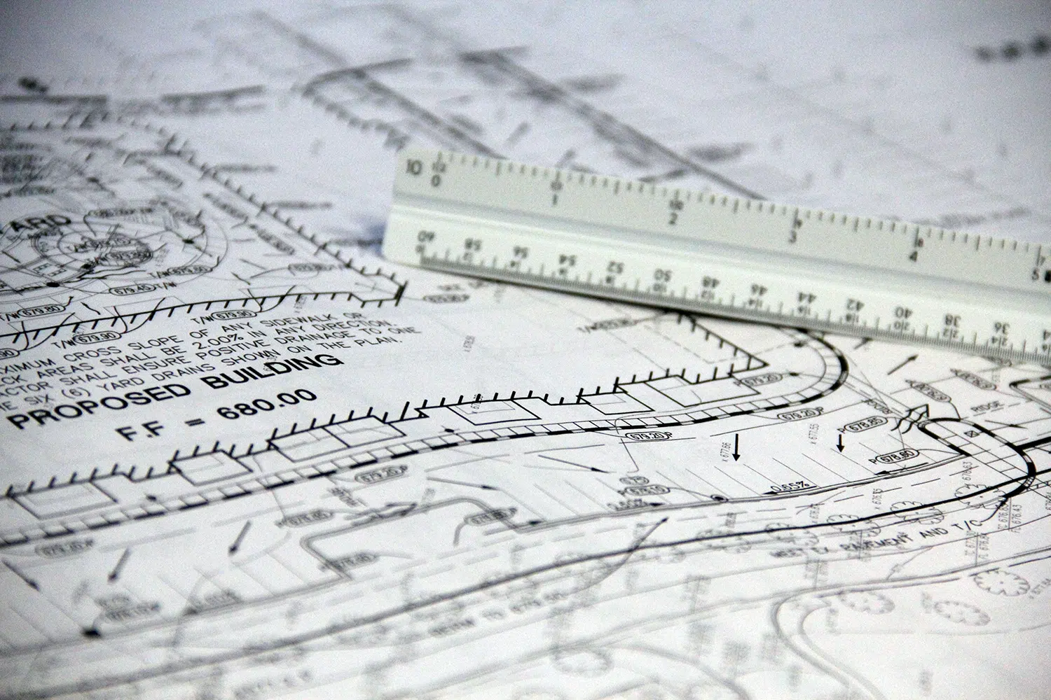
While you don’t have to be an engineer to interpret engineering, drafting & code drawings, knowing how to do so can help you in many ways.
What Is the Purpose of Engineering Drawings?
Engineering drawings (also known as blueprints, manufacturing blueprints, prints, manufacturing prints, dimensional prints, drawings, mechanical drawings, and other terms) are detailed sketches that illustrate all of the information and specifications needed to build a certain item or product. It is a graphical language that transmits thoughts and information, not just a drawing.
Related Post: Different Types of Engineering Drawings
Why Not Use A 3D Model Instead?
An engineering design, unlike a 3D model, has a lot more particular information and needs, such as:
- Dimensions
- Finish
- Geometry
- Hardware
- Tolerances
- Type of material
3D Model
3D models are useful and frequently used in conjunction with drawings. They provide a decent visual depiction of the desired object, but they lack the detail that drawings provide.
Blocks of Information
The information included in these blocks is crucial to the assembly. They are frequently seen at the drawing’s bottom right-hand corner. These blocks define what the drawing is for, who it is for, the component number and description, and material and finish information.
The following are the primary data blocks:
Title Block
Begin by reading the title block, which may be located in the drawing’s bottom right-hand corner. Additional information blocks are similar, but the title block serves as the context for seeing the drawing.
The title block includes details such as:
- Material
- Mass
- Finish
- Tolerances in general
- Specifics of the projection
- The scale of the drawing
- Numbers of revisions
- The drawing’s current state (Preliminary, Approved, etc.)
- The firm or organization that created or owned the drawing’s name and address
- Identification of the part and its description
The following are the units that were used in the drawing:
Keep in mind that any information in the notes outside the title block that contradicts the title block information should be regarded as correct and should take precedence over the title block information.
Revision Block
The revision block, positioned in the top right-hand corner, displays information about the modifications made to the revision. The Revision Block contains the revision, a description of the changes made, the revision’s date, and the revision’s approval.
Bill of Materials (BOM) Block
The Bill of Materials block (also referred to as a BOM, Schedule, or Parts List) is normally found directly above the title block or in the top left-hand corner. It also comprises a list of all the goods and quantities necessary for the project or assembly. This is used for items that need to be assembled or have hardware attached.
Lines
It’s critical to know each line type and what it means. There are three different kinds of lines:
- Centerlines: created to show the assembly’s exact geometric center. They’re made up of a sequence of shorter and longer dashes.
- Hidden line: Denotes that the edge is hidden behind a face.
- Phantom line: Usually used to show a moving item in a different location. When the object makes using a traditional form of break impossible, this symbol is also used to signify a break.
- Visible line: An edge is visible in the appropriate view.
What’s Next After Reading Engineering Drawings?
Now is the time to imagine how the assembly should look in 3D. The majority of new designs will have an isometric perspective to assist you. The Bill of Materials may be used to locate components in the design and determine their function in the assembly.
Conclusion
Remember that, depending on the intricacy of the assembly and the reader’s expertise, reading an engineering drawing might take a long time. If you’d like to learn more, look for a course that will teach you how to read and interpret drawings correctly and give you a deeper grasp of a project’s special requirements. If you also want to look for professional drafting services, you can opt to look for engineering services near you.
T.R. Arnold & Associates specializes in commercial and residential modular construction, prefabricated houses, park trailers, and recreational vehicles. Contact us if you need engineering or drafting services!


